|
|
|
| > |
|
Loading
|
|
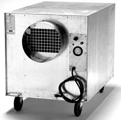
We Have a Model to fit your needs:
MODEL DASH 25GB BIO-SECURITY SYSTEM SPECIFICATIONS
I. SPECIFICATIONS Dimensions: 26"
W x 31" H x 52" L with Side Access Service Door II. STANDARD EQUIPMENT Units are provided with: 12" D reinforced exhaust, 12" diameter direct drive centrifugal blower with a 120 volt motor; control panel with 15 amp circuit breaker, 2 speed switch, pressure gauge, 4 lifting handles, 4 heavy duty swiveling casters (including 2 locking casters). POWER REQUIREMENT Unit may be plugged into 120 volts or 100 volts, 15 amp service with ground. CIRCUIT BREAKER A 15 amp circuit breaker is located in the control panel. When breaker trips, the round button marked “15” will protrude; to reset, turn speed control switch to off position, push in breaker button, and restart unit. If breaker trips again, disconnect power cord and check for loose or damaged wiring. Repairs must be done by a qualified electrical technician. 3 SPEED SWITCH Located in upper right-hand corner of control panel. FILTER GAUGE A minihelic gauge is located in the center of the control panel. Gauge readings will help to determine when to change filters. See Filter Section for further information. III. LUBRICATION Lubricate wheel bearings once a year using automotive grease. IV. MAINTENANCE Filters: 1. Pre-Filters: 24" x 24" ring panel, #15/40, 3-ply to be installed with white side out; the coloredside is downstream. The filter should be replaced when the colored material becomes discolored. The purpose of the pre-filter is to extend the life of the catalytic reaction element and HEPA filter, while keeping the anti-microbial elements clean. Be sure to have a replacement supply of these filters and elements in stock. 2. HEPA Filter 24" x 24" x 4": The purpose of the filter is to collect media dust and dust particles 0.3 micron size and larger. The life of the HEPA filter is up to 2 years. To replace the HEPA filter and the catalytic reaction chamber, unscrew 4 –3 /8" nuts securing the HEPA and chamber. Each rod has a retainer block to hold the HEPA and chamber in place. Finally, remove the filter and chamber. Caution: HEPA filters are to be handled only by their frame. Do not touch the white media or separators as damage could result. 3. Catalytic Reaction Chamber: The purpose of the chamber is to assist in the killing of bacteria and removal of VOCs. Catalytic reaction chamber is 24" x 24" x 12". The life of this chamber is up to 12 months. 4. Anti-Microbial Elements: 16 – IAF Anti-microbial elements need to be replaced every twelve (12) months. To replace anti-microbial elements, remove side access door. Remove elements from holders in the filter frame by pushing up and turning each element to remove the elements. Replace with IAF anti-microbial elements following same procedure. Be careful when removing anti-microbial elements from holder; wear clean gloves during this operation. Replace with new IAF anti-microbial elements using clean gloves. DO NOT TOUCH ELEMENTS WITH BARE HANDS. Once new elements have been replaced, re-install all filters and side access door per enclosed instructions. To operate efficiently, elements must be clean at all times. Anti-microbial elements can be cleaned with rubbing alcohol applied with a clean cloth. V. WARNING: 1. IN ORDER FOR OUR EQUIPMENT TO BE EFFECTIVE, FILTERS, CHAMBER AND ELEMENTS MUST BE CHANGED REGULARLY. BEFORE HANDLING OR REPLACING CONTAMINATED FILTERS OR ELEMENTS, CONTACT YOUR LOCAL HEALTH AUTHORITIES TO DETERMINE PROPER HANDLING AND DISPOSAL PROCEDURES. 2. DO NOT CHANGE FILTERS, CHAMBER OR ELEMENTS WHILE UNIT IS TURNED ON, AND NEVER LOOK DIRECTLY AT THE ANTI-MICROBIAL ELEMENTS WHEN THE UNIT IS TURNED ON.
3. USE OF OUR EQUIPMENT OFFERS NO GUARANTEE THAT INDIVIDUALS WILL NOT BE INFECTED. OUR EQUIPMENT IS ONLY ONE STEP AMONG OTHERS TO PROTECT INDIVIDUALS FROM HARMFUL PATHOGENS. FURTHERMORE, WE KILL ONLY PATHOGENS THAT PASS THROUGH EQUIPMENT. ALTHOUGH WE CANNOT CLAIM ANY SPECIFIC CAPABILITIES OF OUR FILTRATION SYSTEMS AT THIS TIME, WE FEEL WE CAN PROVIDE YOU WITH SOME PROTECTION FROM THESE AGENTS. VI. WARRANTY Motor, blower, and switch - 2 years parts and labor We Have a Model to fit your needs: |
|
Copyright © 2005 Shilog Medical Supply | Site Map | Contact Us |